


Perform with FCC S.A.
Join our Content Team to create and share knowledge.
Learn how to be part of it


Be acquainted with our purpose, values, history and all that makes the FCC S.A. essence

A portfolio of products and solutions plenty of innovation, technology and sustainability.

To deliver products with leading edge technology and global quality is just our starting point. That is why we have a series of exclusive services for our customers and that make all the difference on a daily basis.

See in practical terms how innovation is present in the FCC S.A. DNA

Sustainability is present in every solution, delivery and process of our company: learn more.

We are made of synergy! Learn how you can become a FCC S.A. supplier

Learn how it is to work with FCC.S.A. Learn our culture, programs and check for opportunities.

Integrity and transparency are part of what we are. Check our annual reports and see the result of our work.

Find a variety of contents that permeate our businesses and see how you can be a part of what we create around here.

Together, we create more! Be a FCC S.A. partner and generate value for a world in transformation: learn how.

The catalytic cracking units operate by circulating a solid catalyst inside the converter. The main responsible for the occurrence of this circulation is the pressure balance.
The Pressure balance relates to the catalyst circulation hydraulics between the separator vessel and the regenerator. This catalyst behaves as a fluid when aerated by stream in the vapor phase. In this way, the catalyst flow in the FCCU occurs by pressure differential. That is why the catalyst should be kept fluidized during the converter cycle.
The fluidized catalyst behavior is similar to that of a fluid and its flow occurs in the direction of the lower pressure. The pressure differential between two spots in a bed is equal to the bed length between these spots multiplied by the fluidized catalyst density. Therefore, the converter set of a catalytic cracking unit is essentially the system filled with water illustrated in figure 1.
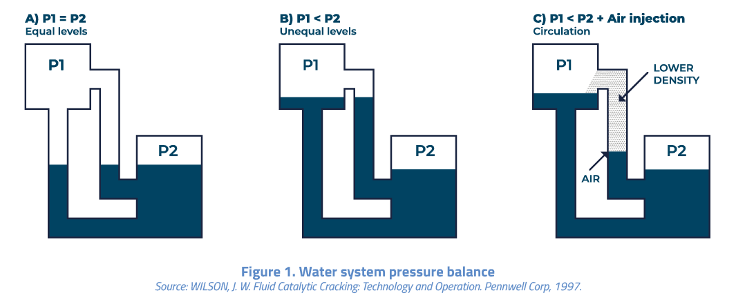
As can be observed in figure 1A, in case the pressures in the two vessels are the same, the water level will also be the same. On the contrary, in figure 1B, in vessel 1 the pressure is smaller than that of vessel 2, consequently, the water level will rise, as illustrated. Finally, in figure 1C, in case air or another gas is injected into the riser connecting the two vessels, the water level in this line will rise still more due to the density reduction in this area. By injecting in the riser a sufficient amount of water vapor, there will be overflow towards vessel 1 and the system circulation will be established.
This is the process utilized in a FCCU to circulate the fluidized catalyst. Typically, the separator vessel is equivalent to vessel 1 and the regenerator, to vessel 2. The riser density is lower as a function of the presence of the feed and the products vapors, besides the water vapor injection and, for this reason, the catalyst shows upwards flow in the riser up to the separator vessel.
The main components of a FCCU converter pressure balance are the regenerator, the regenerated catalyst piping, the temperature control valve at the riser top (TV) of regenerated catalyst, the riser, the separator vessel, the spent catalyst piping and the catalyst level control valve in the spent catalyst separator vessel (LV). The pressure balance determines the pressure fall available in the two valves.
The mastery of the pressure balance is extremely important for the unit optimization. The FCCU capacity can be incremented, for example, based on higher catalyst circulation or by altering the pressure differential between the separator vessel and the regenerator, to render possible two usual restrictions found in the catalytic cracking unit, the blower and the compressor flow rates. Therefore, the main objectives of the Pressure balance are:
Finally, the Pressure balance is paramount to secure that the catalyst always flows from the regenerator towards the separator vessel, and later, returns to the regenerator. The flow inversion in the converter set, in the TV case will enable the feed injected in the riser to enter the regenerator, significantly increasing the temperature of same, which inexorable will entail a unit shutdown. In an analogously way, the flow inversion in the converter set considering LV will enable the flow of combustion gases with presence of oxygen to the separator vessel, and consequently, temperature rise in the separator vessel, it being necessary to stop the unit operation.
Related Publications


What did you make of the publication?