


Perform with FCC S.A.
Join our Content Team to create and share knowledge.
Learn how to be part of it


Be acquainted with our purpose, values, history and all that makes the FCC S.A. essence

A portfolio of products and solutions plenty of innovation, technology and sustainability.

To deliver products with leading edge technology and global quality is just our starting point. That is why we have a series of exclusive services for our customers and that make all the difference on a daily basis.

See in practical terms how innovation is present in the FCC S.A. DNA

Sustainability is present in every solution, delivery and process of our company: learn more.

We are made of synergy! Learn how you can become a FCC S.A. supplier

Learn how it is to work with FCC.S.A. Learn our culture, programs and check for opportunities.

Integrity and transparency are part of what we are. Check our annual reports and see the result of our work.

Find a variety of contents that permeate our businesses and see how you can be a part of what we create around here.

Together, we create more! Be a FCC S.A. partner and generate value for a world in transformation: learn how.

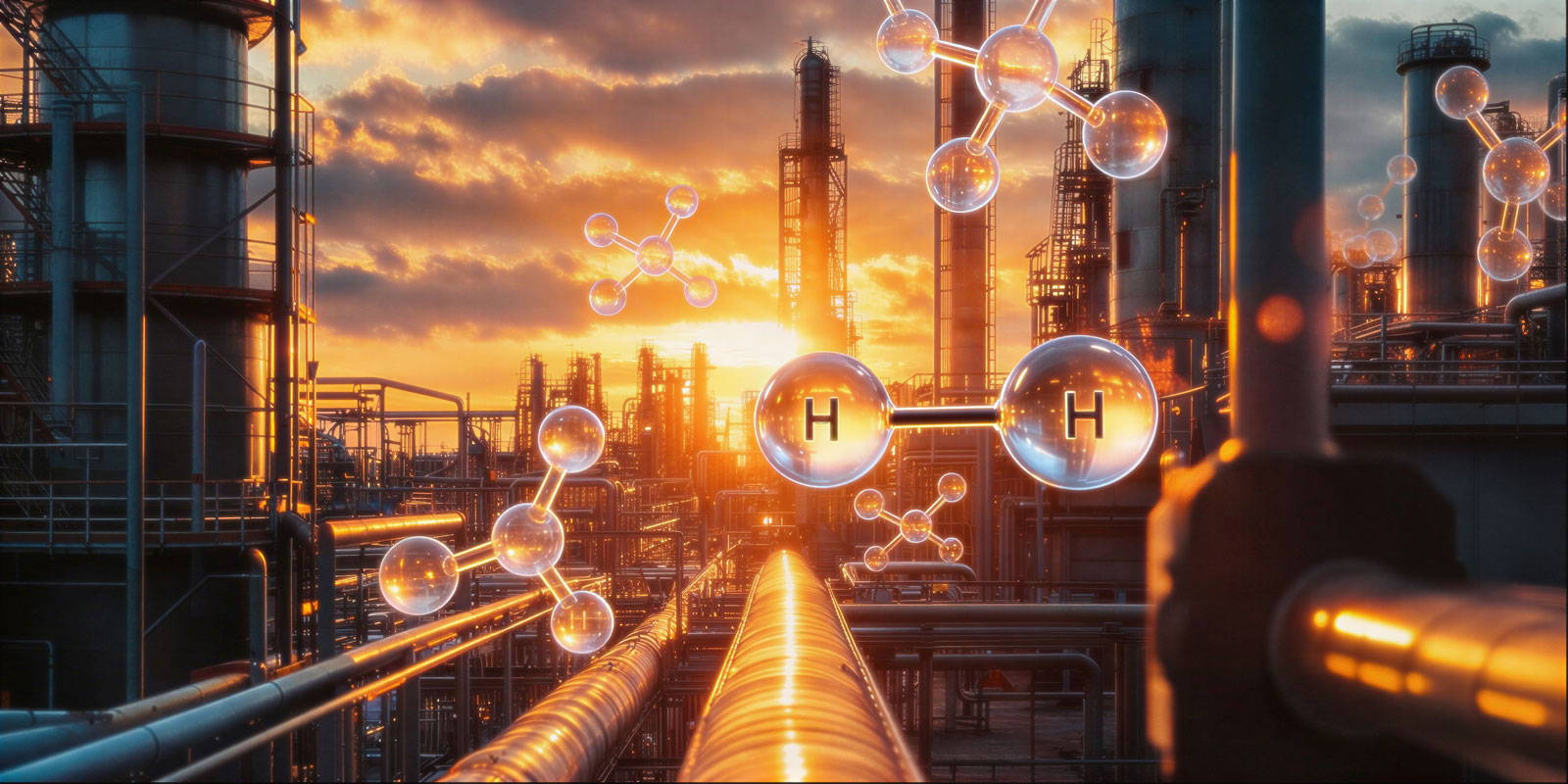
In scenarios of geopolitical instability with global economic repercussions, refineries tend to intensify strategies aimed at maximizing production, optimizing processes, controlling costs, and increasing profitability. In this context, changes in the processed crude slate tend to become more frequent, resulting in changes in the feedstock composition of units of fluidized catalytic cracking (FCCU).
Among the main metallic contaminants present in crude oil, nickel (Ni), vanadium (V), iron (Fe), and sodium (Na) stand out. Variations in the concentrations of these metals and in the characteristics of the crude oil require continuous monitoring of the feedstock quality, and it is the role of process engineering to act proactively to mitigate impacts on the unit and the catalyst.
Although nickel does not promote degradation of the zeolite crystal structure, as occurs with vanadium, its high dehydrogenating activity can cause significant operational impacts, imposing restrictions associated with the gas compressor, leading to a reduction in processed feed and requiring a decrease in operational severity. For more information on the impacts of nickel on FCCU performance, please visit the FCC S.A. technical brief: “H2 and its impacts on FCCU performance” [1].
One of the strategies used to mitigate the effects of nickel is the injection of passivating additives, the most common being those based on antimony (Sb) or, to a lesser extent, bismuth (Bi). In industrial practice, solutions containing antimony pentoxide (Sb2O5) are predominantly used due to their greater passivation efficiency. Bismuth-based compounds are already being used as an alternative to antimony, due to the potential occupational and environmental risks associated with this element [2].
Operationally, controlling the dosage of this additive is critical. Improper injection can compromise both operational performance and unit costs. When dosed in excess, antimony tends to preferentially migrate to the bottom stream of the main fractionator, which can cause:
One important aspect is that excess antimony is not detectable through e-cat analysis, as its deposition to the catalyst depends on the presence of nickel available for complex formation. In the absence of nickel available for the reaction, antimony migrates to the slurry oil stream.
Practical indicators of overdose:
To avoid problems caused by excess additive, the necessary amount of antimony to react with nickel must be calculated in order to maintain the balance of the reactions, without excesses. To calculate the optimal injection rate of this additive, it is important to consider the following factors:
Formula for calculating the flow rate of antimony solution in L/d:

Where:
mfeedstock = Mass flow rate of feedstock in t/d;
Nifeedstock = Nickel concentration in the feedstock in ppm;
Sb/Ni = Ratio according to theory, from 0.1 to 0.5;
nsb = Retention of the antimony solution (from 0.65 to 0.85);
Csb = Mass concentration of the antimony solution (from 0.17 to 0.30);
psb = Density of the antimony solution in kg/L.
The calculated value should always be validated and adjusted based on the responses of the unit’s operational variables, primarily: H2 concentration in the fuel gas, coke formation, and Sb/Ni ratio in the e-cat.
The components incorporated into the catalyst formulation to suppress the dehydrogenating activity of nickel are called “nickel traps”. FCC S.A. catalysts contain a high-performance nickel trap called ADM-60 in their formulation, the concentration of which can be adjusted according to the specific needs of each unit.
The mechanism of action occurs through the formation of spinel-like structures, in which nickel reacts with the catalyst matrix, forming nickel aluminate (NiAl2O4), a stable spinel-like crystalline phase (Figure 1). Under typical FCC operating conditions, the formation of the non-stoichiometric phase NixAl2O3+x is also common. These reactions occur primarily at high regenerator temperatures in an oxidizing atmosphere (680-730 °C). Due to the high thermodynamic stability of spinel compounds, their reduction to the Ni0 metallic phase is significantly hindered under riser conditions, characterized by a reducing atmosphere and temperatures between 500–550 °C. Consequently, greater tolerance of the catalyst to nickel contamination is observed, with a significant reduction in dehydrogenating activity associated with this contaminant. This behavior has been reported in the literature through temperature-programmed reduction (TPR) analyses.
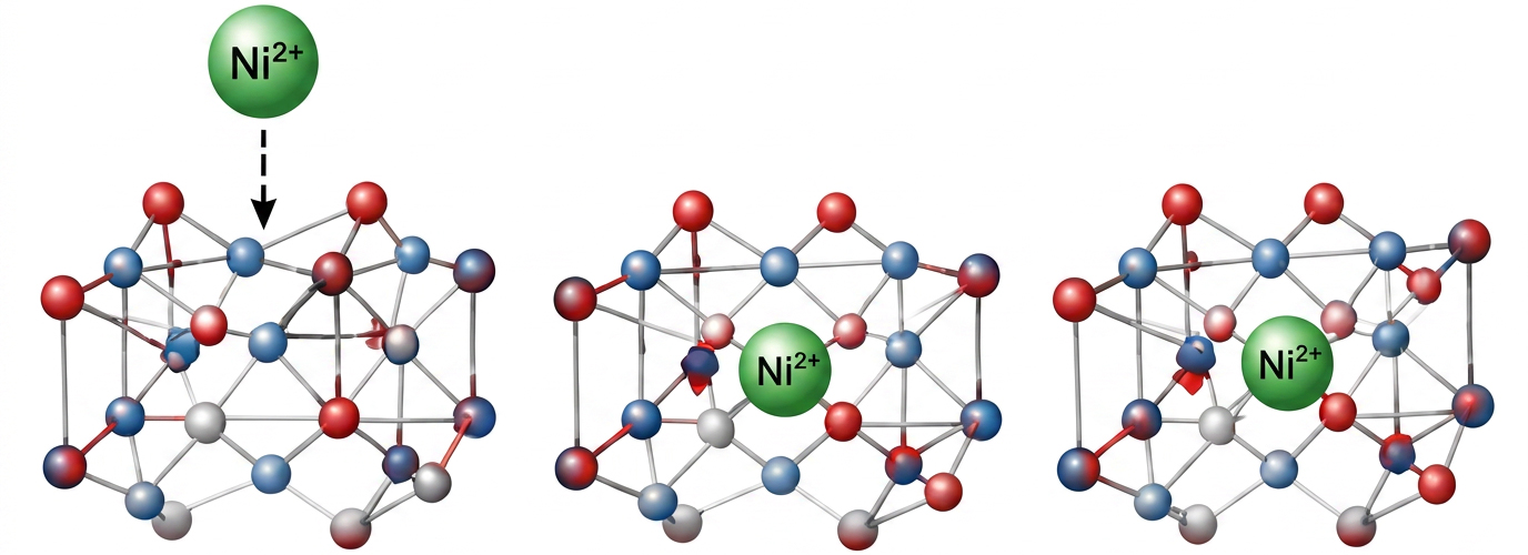
Figure 1: Formation of a spinel-like structure.
Source: FCC S.A. Database.
This trap approach (formation of a spinel structure) is superior when compared to other passivation approaches, such as those based on adsorption by Lewis acid-base interaction (Figure 2). In this model, the Ni2+ cation (Lewis acid) is retained by coordination interactions with basic sites of the catalyst matrix, such as surface groups, commonly based on MgO or La2O3 [5]. Although this interaction limits the mobility and sintering of nickel, the stability of the species formed is considerably lower than that of spinel: under the reducing conditions of the riser, an atmosphere rich in hydrocarbons and hydrogen at 500–550 °C, adsorbed Ni2+ can be partially reduced to metallic Ni0, a species highly active in dehydrogenation reactions. Thus, although the Lewis acid-base model reduces the mobility and sintering of nickel, its effectiveness in suppressing dehydrogenating activity is inferior to that provided by the spinel model, in which nickel is incorporated into a thermodynamically stable crystalline structure that is difficult to reduce.
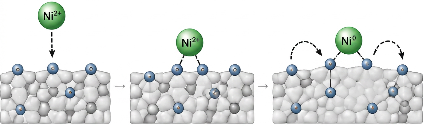
Figure 2: Lewis model of adsorption or acid-base binding.
Source: FCC S.A. Database.
To illustrate the effectiveness of nickel passivation of FCC S.A. catalysts, Table 1 shows the results related to this subject from a catalyst evaluation with an 80% inventory exchange from a catalyst from another manufacturer to UPGRADER™, which contains a Ni passivator in its formulation.
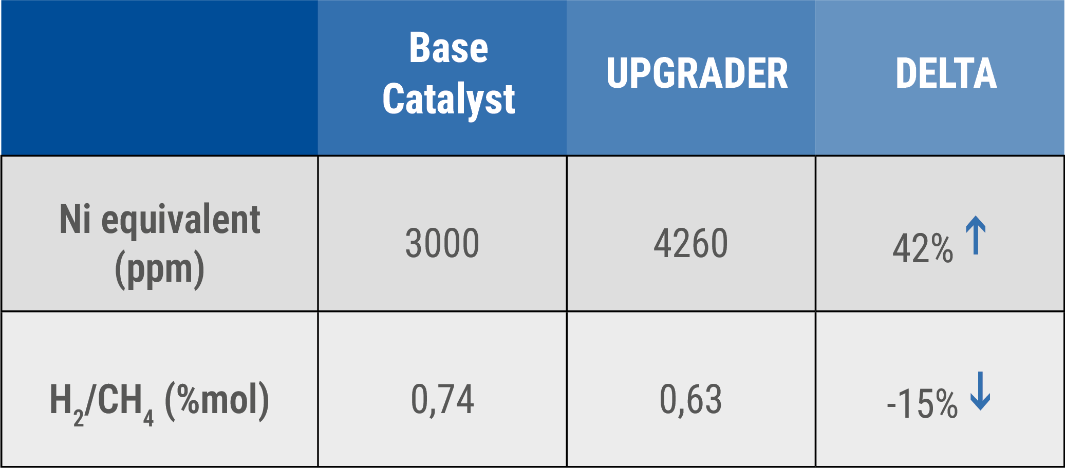
Table 1: UPGRADER™ Evaluation Results.
Source: FCC S.A. Database.
The FCC S.A. catalyst, when compared to the base catalyst, showed a significant reduction in the H2/CH4 ratio, even with an increase in the amount of nickel equivalent, indicating better product performance, which incorporates FCC S.A.’s ADM-60 nickel passivation technology. In addition to UPGRADER™, technologies such as DENALI® and SaFeGuard™ have also been developed for processing heavy feed and possess high resistance to metals.
Nickel passivation through antimony injection is an important tool for reducing the effects of nickel in FCC units, especially in scenarios involving the processing of more contaminated feedstock. However, its application requires strict control, since overdosing can result in significant operational impacts, as well as economic losses. Therefore, periodic review of the dosage calculation and adjustment of the product addition is recommended.
Additionally, the use of catalysts with integrated passivation technologies represents an effective and well-established strategy to reduce dependence on additives, increase operational robustness, and improve process profitability. To achieve maximum performance from catalysts, it is important to preserve inventory quality through optimal and continuous make-up with fresh catalyst.
FCC S.A., through its Technical Services team, offers total support to refineries in evaluating, optimizing, and maximizing the performance of FCC units. Our solutions include, for example, antimony dosage and metal balance studies, as well as constant analysis of the suitability of the catalyst formulation aligned with the specific operational challenges and objectives of each unit.
Related publications


What did you make of the publication?