


Perform with FCC S.A.
Join our Content Team to create and share knowledge.
Learn how to be part of it


Be acquainted with our purpose, values, history and all that makes the FCC S.A. essence

A portfolio of products and solutions plenty of innovation, technology and sustainability.

To deliver products with leading edge technology and global quality is just our starting point. That is why we have a series of exclusive services for our customers and that make all the difference on a daily basis.

See in practical terms how innovation is present in the FCC S.A. DNA

Sustainability is present in every solution, delivery and process of our company: learn more.

We are made of synergy! Learn how you can become a FCC S.A. supplier

Learn how it is to work with FCC.S.A. Learn our culture, programs and check for opportunities.

Integrity and transparency are part of what we are. Check our annual reports and see the result of our work.

Find a variety of contents that permeate our businesses and see how you can be a part of what we create around here.

Together, we create more! Be a FCC S.A. partner and generate value for a world in transformation: learn how.
In this article we will rapidly address some of the main influences applied by other refining units on the FCC and which influences the FCC exerts on them by focusing on a few units present in the most common refining schemes.
In a refining scheme each unit has its own role, which was studied and planned to achieve a goal in the refinery, contributing with its share to the end-products quality or for the fulfillment of legal requirements. Among feeds, products and effluents, several hydrocarbon streams are forwarded from one unit to the other until they leave the refinery in their final form.
Each unit influences the other ones in several ways, and understanding what an adjustment or disturbance in one unit causes on the other ones is part of the essential knowledge of the Process Engineer working in refining processes, since the goal is not only each unit optimization but also that of the refinery as a whole.
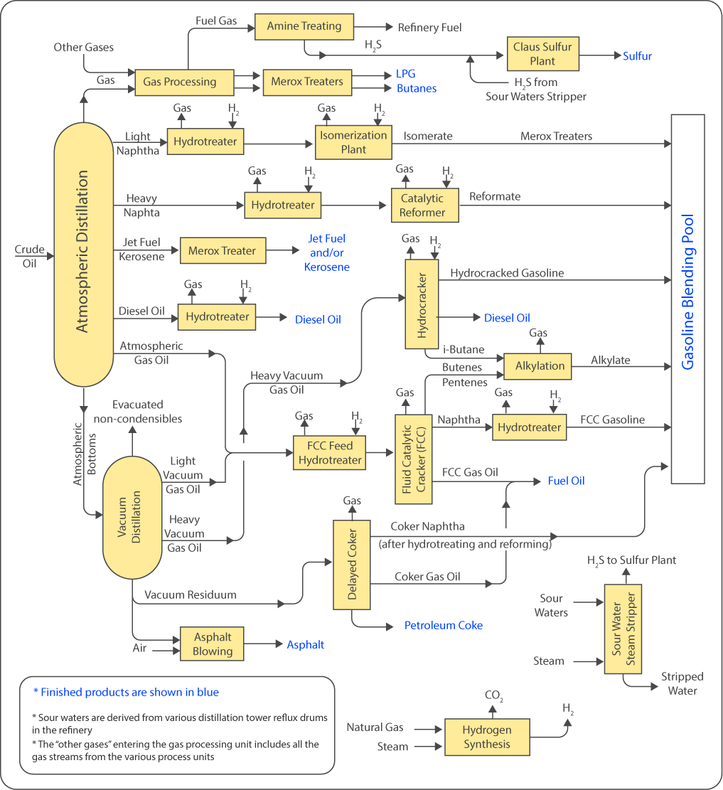
Figure 1 – simplified refining process scheme. Source: (1)
The distillation unit is the catalytic cracking units main feed source. It is in this unit that not only the first separation of crude into products occurs, but also the first crude treatment, which will affect practically all the other refinery units: desalting. In many refineries FCC also receives from distillation units light hydrocarbon streams such as fuel gas and LPG, that are fed to the main fractionation column or gas recovery section to be treated along with the converter products.
The fractionating quality of the distillation unit directly influences the FCC. Several hydrocarbon streams from this unit can integrate the FCC unit load, such as:
The presence of both light and heavy hydrocarbons affects the FCC unit. Light hydrocarbons, with boiling point below 340ºC, which could be recovered as diesel, are usually refractory to catalytic cracking and it is expected that most of them leave directly as LCO. Additionally, partial feed vaporization can occur after final heating, leading to drawbacks on feed flowrate control for the nozzles. In case of extensive heavy diesel oil degradation to the FCC feed, a reduction in decanted oil BMCI may occur, impairing the production of feedstock for carbon black.
For gasoil processing units, the presence of very heavy fractions, originating from the entrainment of vacuum residue droplets to the gasoil or from the AR processing increases concentration of contaminants such as vanadium, nickel and iron, which cause catalyst deactivation and increase coke and fuel gas production. In these cases, to keep catalyst inventory healthy, catalyst make-up must be increased. The presence of these hydrocarbons also increases the FCC unit feed carbon residue, leading to increased coke yield, conversion reduction, dense phase temperature increase and increased unit air demand.
Efficient desalting is crucial for corrosion, contaminants content and deposits control, not only in the distillation unit but also in downstream units. Together with the brine, water, salts (especially chlorides, but also other salts), metal oxides (corrosion products), sand and other wastes are expelled (2).
Efficient desalting depends on providing the required amount of water, adequate mixture, crude viscosity and maintenance of suitable electrodes tension. Special attention should be given to heavy oils since they require higher temperatures for adequate process viscosity. Generally, additives are used to hinder emulsion formation caused by the presence of surfactants in crude oil.
Appropriate salts removal, mainly chlorides, is the desalting’s goal. Calcium and magnesium chlorides, less soluble and more difficult to remove, can undergo hydrolysis in the distillation unit furnaces, the released chlorine causing severe corrosion at the fractionation columns’ overhead (atmospheric and vacuum), as well as contaminating end products, especially Light Vacuum Gas Oil. To prevent this phenomenon, many refineries add caustic soda to crude oil, to transform these salts into NaCl, which does not hydrolyze and tends to concentrate in the residual streams (AR or VR). Appropriate desalting inhibits the use of high amounts of this chemical.
Inadequate desalting causes increased presence of contaminants in the FCC unit feed, which affects the unit in several ways:

Figure 2 –Desalter. Source: (2)
Since the distillation unit produces low fuel gas and LPG flowrates, many times there are no captive units for treating these streams and they are conveyed to other units for processing. A classic project configuration is the destination of these streams to the FCC unit: fuel gas is generally directed to the main fractionator’s overhead drum, while LPG can be forwarded to the same location, to the debutanizer feed or directly to the treating section. This external stream reception can result in a few consequences for FCC:
Cracked naphtha is an unstable and corrosive product, high in sulfur, olefins, diolefins and other gum precursors. To comply with gasoline specifications, it should be submitted to treatments to remove such contaminants, and in response to low-sulfur gasolines demand there is a growing need to hydrotreat this product.
Hydrotreatment reactors employ fixed bed catalysts and hydrogen to remove contaminants such as sulfur, nitrogen, oxygen and even aromatics from the treated streams, depending on process severity and on the chosen catalyst.
In most refineries, the process scheme contemplates a hydrotreatment unit dedicated to sulfur removal from cracked naphtha. This unit should be prepared to deal with the presence of diolefins and to selectively remove sulfur without saturating olefins to preserve this naphtha’s octane, which is most important for gasoline composition.
Very often, a load reduction or shutdown of the cracked naphtha hydrodesulfurization unit implies in the need of FCC unit load reduction or shutdown, since as a function of its instability cracked naphtha cannot have contact with oxygen before being sent to the hydrodesulfurization unit. Oxygen contact can cause gum formation which will cause obstructions in the reactors. Units not equipped with inert cracked naphtha storage tanks should directly convey the FCC unit produced naphtha to the hydrotreatment unit.
Many refineries also profit from this unit’s eventual surplus capacity to treat a portion of the direct distillation naphtha produced in the refinery. Naphtha streams originated from delayed coking units or other thermal conversion units, however, require more severe treatment and it is not common for them to be conveyed to cracked naphtha treatment units.
Hydrotreating units, and especially their catalysts, are designed to perform well for a certain time under pre-defined flowrates and load qualities. Changes in these two parameters affect catalysts’ deactivation and determine their actual lifespan. Once deactivated, catalysts should be unloaded and substituted. The higher the feed flowrate and the reaction temperature (usually expressed as WABT - Weighted Average Bed Temperature), the more accelerated the deactivation mechanisms become. The pressure drop in the catalytic bed can be an additional restriction, reducing the unit’s capacity (3,4).
Since FCC is the source of basically 100% of th unit’s feedstock, it clearly exerts a huge influence on the cracked naphtha hydrodesulfurization unit. At the same time, it is necessary to perform adjustments in the FCC unit to comply with the treating unit’s restrictions and needs. We will share a few comments on some of the main ones:
Dienes are highly unstable compounds, which tend to react among them forming polymers on the catalyst (gums) which increase pressure drop in the bed and can limit the hydrotreating unit load. These polymers also form coke on the catalyst’s surface, causing its deactivation. Furthermore, these compounds’ hydrogenation reactions are highly exothermic, and an excessive rise in hydrotreating reactors’ temperature can even lead to mercaptans formation (desulfurization reversal). That is why many naphtha hydrodesufurization units have a reactor dedicated to converting diolefins into simple olefins, which prevents these compounds to reach the hydrotreating reactors.
Selective diolefins hydrogenation reactors usually operate at low temperatures, naphtha being just partially vaporized, and low hydrogen availability, thus hydrogenating diolefins and avoiding olefins hydrogenation as much as possible to preserve the naphtha’s octane (5).
The cracked naphtha’s diolefin content is determined in the FCC unit and both the converter adjustments and those of the fractionation process interfere in this parameter, usually determined by the Maleic Anhydride Value (MAV), defined by the Maleic Anhydride amount (in mg) required to react with 1 g of cracked naphtha by the Diels-Alder mechanism (ASTM UOP326-17) (7). The factors which most influence cracked naphtha MAV’s are:
Naphtha’s diolefin content directly influences the hydrodesulfurization unit catalyst’s longevity, not only that of the selective hydrogenation reactors, but also that of the desulfurization reactors. The presence of diolefins, even at residual concentrations, leads to polymers and coke formation on the catalytic bed, leading to gradual activity loss and increased pressure drop, factors that reduce the time between turnarounds and unit’s capacity. It is important to control the cracked naphtha hydrodesulfurization unit feedstock’s MAV close to the design value throughout the campaign, allowing the unit to operate for the intended time.
Generally, sulfur concentration in cracked naphtha is the main restriction for its incorporation into the gasoline pool. That is why hydrodesulfurization units become crucial in a low and ultralow sulfur content context, because cracked naphtha’s concentrations are usually in the order of hundreds or even thousands of parts per million of this contaminant, depending on the quality of the feed and unit adjustments.
Most refineries’ strategy is to reduce cracked naphtha’s sulfur concentration beyond the gasoline specification, enabling the incorporation of a fraction of non-hydrotreated streams into the final gasoline pool. To attain the sulfur target concentration, the hydrodesulfurization unit’s feed and effluent is analyzed and WABT and hydrogen partial pressure are variated to adjust reactions.
The higher the feed’s sulfur content and the more refractory this sulfur is the higher the severity required to treat naphtha and the higher also the unit’s hydrogen consumption. Therefore, the catalyst’s lifespan is intimately linked to the concentration and the kind of sulfur compounds present in naphtha, these two factors being controllable, at least in part, in the FCC unit.
Despite being very dependent on the FCC feed, a few adjustments in fractionation and in the catalytic system make it possible to manage sulfur in cracked naphtha, the concentration of which is usually between 5% and 10% of the feed sulfur when the feed is not hydrotreated.
One of the existing alternatives is the use of catalyst additives to reduce naphtha’s sulfur. These additives work as a fine tuning, enabling to successfully reduce naphtha’s sulfur content by intervening in sulfur compounds formation processes and reacting with these compounds. However, it is important to know where is this sulfur directed to when it is no longer in naphtha: part of it forms H2S and part goes to coke, then, to avoid SOx emissions increase, suitable additives should be used. Furthermore, it is mandatory to know if this kind of solution is applicable or not to your catalytic system and converter type, especially for units working with a high vanadium content inventory, since vanadium competes with the naphtha sulfur reducing additive, decreasing its efficiency.
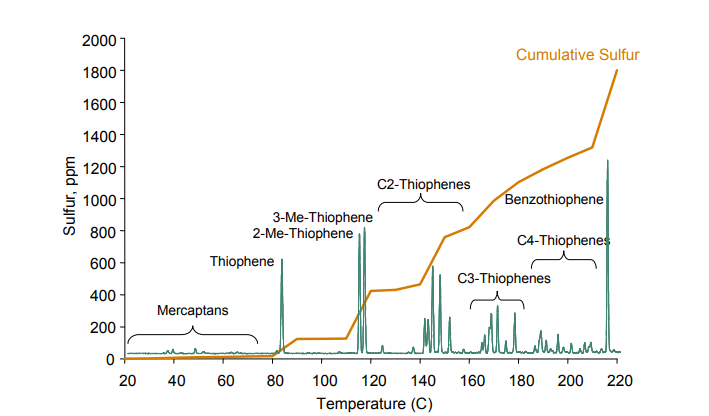
Figure 3. – Cracked naphtha sulfur content as a function of boiling point. Source:(8)
In terms of sulfur content, the most usual adjustment is the cracked naphtha’s final boiling point adjustment. As can be seen in Figure 3, different species of sulfur compounds are distributed along the naphtha distillation curve, with the more refractory compounds, that have higher impact on concentration, being situated in the higher boiling point range. That is why, in many refineries, when total sulfur reduction is required, a naphtha’s final boiling point adjustment is made through the fractionator column overhead’,s temperature reduction. There are also refineries where this adjustment is performed in a specific fractionator for naphtha. In both cases, the generated heavy naphtha, with more sulfur, can be conveyed to diesel along with LCO.
In addition to the compounds shown in the curve, for most of cracked naphtha it is possible to detect compounds that have boiling points beyond the final point usually expected for a naphtha stream. This occurs because of heavy compounds entrainment, either sulfur compounds or not, caused by fractionation inefficiencies. The worst the fractionation is, the higher these compounds’ concentration.
The strategy of naphtha boiling point’s reduction can bring some relevant impacts which should be taken into consideration, not all of them being obvious:
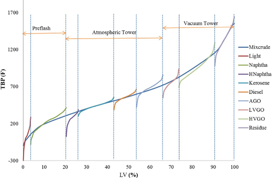
Figure 4 – Distillation curves for the different products– Source: (9)
Salt formation at the main fractionator column overhead: overhead column temperature’s reduction to values below the ammonium chloride deposition point can lead to build-up of these salts in the internals, which in addition to causing severe corrosion leads to a decrease in the fractionation quality due to inefficient liquid-vapor contact, whichconsequently leads to the entrainment of heavier compounds which should have been kept in the heavy naphtha streams and LCO.. Inefficient fractionation rises light naphtha’s final boiling point and increases its sulfur content, which makes the refinery further reduce the column’s overhead temperature, causing a cumulative effect which will only be solved by cleaning the internals. These deposits can be mitigated by using salt dispersants, but is it noteworthy to remember that this will convey chlorine salts towards naphtha and diesel hydrotreatment units, where they will possibly cause corrosion, plugging and catalyst deactivation. Ideally, investment should be directed to desalting and to maintain the main fractionator column overhead temperature at least 5°C above the salt deposition temperature, along with avoiding the use of chlorine-containing catalysts.
Liquid water formation at the main fractionator column: in addotion to ammonium salts deposition, aqueous phase formation at the main fractionator column’s overhead region may occur in case the overhead temperature is lower than the water’s dew point. The presence of this water can lead to column instabilities and serious fractionation problems in case no means to remove it are provided, in addition to internals corrosion and damages to heavy naphtha’s pumps.
The sulfur compounds of heavier fractions, which should not be in the naphtha, can represent of up to 40% of the naphtha’s total sulfur. More important than simply reducing the cracked naphtha’s final boiling point is to improve fractionation between naphtha and heavier products, as will be discussed in the next section.
As is well-known, fractionation among refining products is not perfect. It’s usual that adjacent products distillation curves overlap and how much these curves overlap is indicative of the fractionation quality (Figure 4). Fractionation quality is also perceived by analyzing the distillation curves’ “tails”, the more pronounced the differences between initial boiling point and the 10% evaporate’s temperature of and between the 90% evaporation point and the final boiling point the stronger the indication of inefficient fractionation.
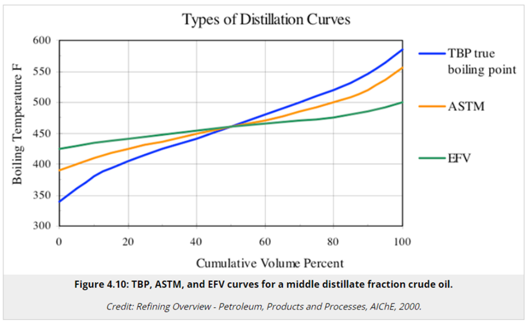
Figure 5 – different distillation curves– Source(10)
It should be also kept in mind that the final boiling point of a certain stream does not preclude the existence, in that stream, of higher boiling point components. Since we are dealing with a naphtha stream, it is usual to run the ASTM D86 analisys in the refinery, while the analysis which would better represent the stream’s effective final boiling point would be the true boiling point (ASTM D2892). (Figure 5)
With those observations in mind, talking about a good naphtha fractionation is not only talking about higher or lower boiling points, but also about separation efficiency , about the existence of higher or lower amounts of hydrocarbons that areheavier than naphtha in this stream. Under convention terms, for FCC’s yield assessments (measured in a true boiling point curve), the standard cut between naphtha and LCO is 221°C.
In naphtha hydrodesulfurization’s reactors, higher molecular weight compounds can form coke on the catalyst, causing its deactivation. Additionally, as previously stated, higher boiling point sulfur compounds are the main contributors to naphtha’s sulfur and are more difficult to remove, requiring increased severity in the unit and reducing catalyst’s lifespan.
In this context, investing in naphtha fractionation, and not simply lowering its final boiling point, is the ideal approach to optimizing cracked naphtha hydrodesulfurization unit’s feed without jeopardizing the FCC unit’s yields and equipment. Many FCC units were built well before hydrotreatment units and were not designed to have a fair fractionation among streams simply because it was not necessary, but even in these units it is possible to improve separation through operational controls in the fractionation columns and favor better liquid-vapor contact, both in the fractionation section between light naphtha and heavy naphtha, which in many columns is rather small, and the section between heavy naphtha and LCO, since many times this fractionation section is larger and adjustments in this section can make the difference. Some of these adjustments are:
FCC fractionation correction opens the possibility to preserve naphtha’s yield and reduce the sulfur sent to the hydrodesulfurization unit by reducing concentration of sulfur compounds that are refractory to hydrotreatment, as shown in the example below:
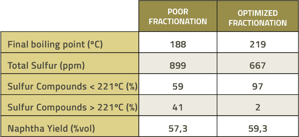
Table 1 – example of sulfur reduction as a function of fractionation adjustment
Related Publications


What did you make of the publication?